Boolean Operations in Autodesk Inventor
BEFORE YOU BEGIN
- Download the dataset. The dataset files were created with Inventor 2011 to ensure compatibility with newer versions of Inventor.
- Extract the zipped file, and save the contents to a project folder of an existing Inventor project. Set the project active. Learn more about Inventor Projects and Project Files.
- Take some time and familiarise yourself with Direct Manipulation in Autodesk Inventor. Check out this lesson: Direct Manipulation in Autodesk Inventor.
INTRODUCTION
A typical solid part is often made up of numerous features that are craftily combined to form the model. When, you are creating such a model in a CAD application like Inventor or AutoCAD, you have to split the modelling operation into various stages. A good designer should be able to quickly determine the feature that should be created first, and those that should be created subsequently. The subsequent features would be combined with the first feature (usually called the base feature) with the help of join, cut, or intersect operations. These are the Boolean Operations in Autodesk Inventor: JOIN, CUT, and INTERSECT. The Boolean Operations are found in the Extrude, Revolve, Loft, and Sweep tools.
OBJECTIVES
At the end of this lesson, the reader should be able:
- Describe the reason for the using boolean operations in your design workflow,
- Describe the three basic boolean operations used in Autodesk Inventor,
- Create simple models using these boolean operations.
JOIN OPERATION
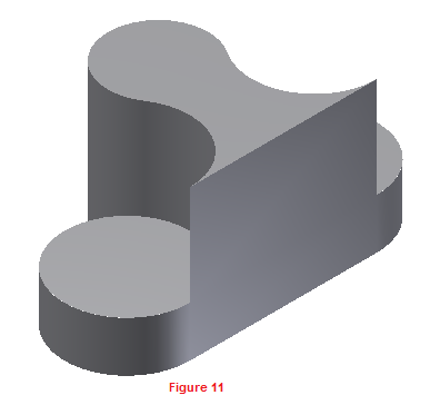
The JOIN operation is used for joining a sketched solid feature to an existing solid feature. The result is a bigger solid that consists of all the volume enclosed by the newly formed sketched feature and the existing solid. In simpler terms, use the JOIN operation to add more features to your base feature.
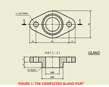
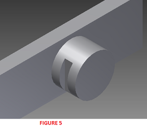
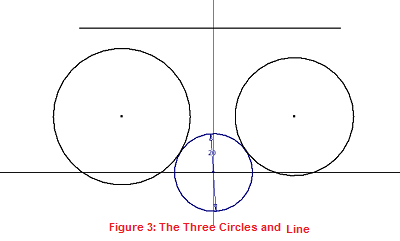
Let's have some fun, by creating the Gland part shown above.
BASE FEATURE
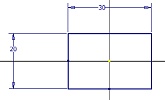
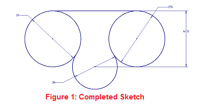
We are going to start by creating the base of the Gland part. The dataset file already contains the base sketch for the Gland.
- Open the file Gland.ipt from the extracted zipped file.
- Press F6 to set the view to the Home view.
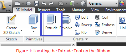
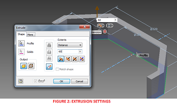
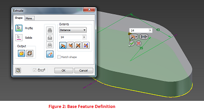
- Press "E" on your keyboard to launch the Extrude tool (or go to Model tab > Create panel > Extrude tool on your Ribbon).
- Set the Extrusion distance to 14mm and click OK or the green tick mark.
CREATING A NEW SKETCH USING A PLANAR FACE
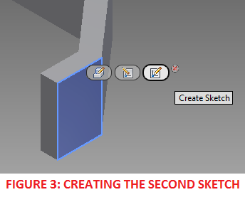
Now, we are going to create a new sketch on the top face of our base feature.
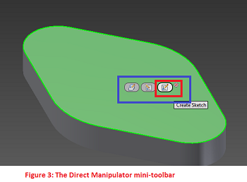
- Click the top of the base feature. The Direct-Manipulation mini-toolbar is display. Click Create Sketch.
- Press Page Up and click the top of the base feature to Look At the new sketch.
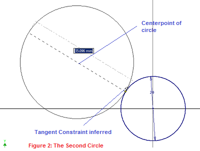
- In the Sketch environment, press C to launch the Circle tool. Click the centerpoint of the sketch as the center of the circle.
- Type 55 as the diameter of the circle, and press the Enter key.
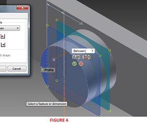
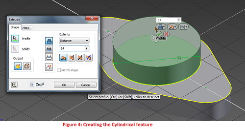
- Press F6 to view the sketch in the Home view. Press E to launch the Extrude tool.
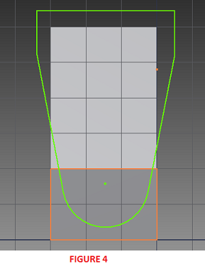
- To select your extrusion profile, click inside the 55-mm diameter circle. Use 14mm as the extrusion distance. Leave other settings as they are. Use Figure 4 as your reference.
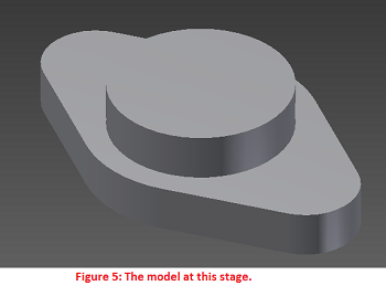
- Click OK to finish the feature.
CUT OPERATION
The CUT operation is used for cutting a sketched feature from an existing solid feature. The result is a new solid that encloses the volume enclosed by the original solid but not by the newly formed sketched feature. In other words, the CUT operation subtracts the volume defined by the new sketched feature from that of the original sketched feature.
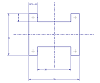
Let's demonstrate this by creating a hole from the center of our Gland part.
- Click on the top face of the newly-created cylindrical feature. Click Create Sketch.
- Press Page Up and select the top face of the cylinder to Look At the Sketch. Press C to launch the Circle tool.
- Click the center of the sketch as the center of the circle, and type 36 as the diameter of the new circle.
- Press F6 to return to the Home view. Press E to launch the Extrude tool.
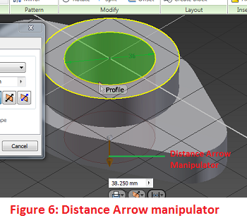
- Click within the 36-mm circle as the profile.
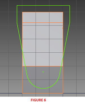
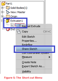
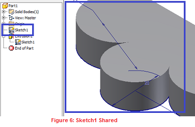
- Click the Distance Arrow manipulator and drag it downwards, making it cut through the solid model (See Figure 6).
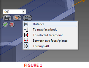
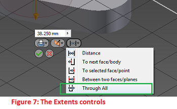
- Go to the In-Canvas Display > Extents control > Select Through All.
- Click OK.
- Go on and add other features. Have fun.
Points to Note:
- By clicking and dragging the manipulator through the existing solid, the system changes the boolean mode from Join to Cut. Drag the manipulator above and through the model and observe the subtle changes in the Extrude dialog box.
- You could explicitly specify the Cut operation by clicking Cut on the Extrude dialog or via the In-Canvas display.
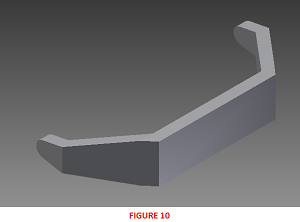
INTERSECT OPERATION
The INTERSECT operation creates a new feature or solid by retaining the volume common to the existing sketched feature and the newly formed sketched feature.
Let us create an interesting design using the INTERSECT operation.
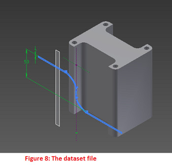
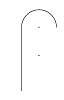
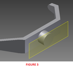
- Open the file DataSet_Intersection.ipt. The file contains an extruded feature and an unconsumed sketch.
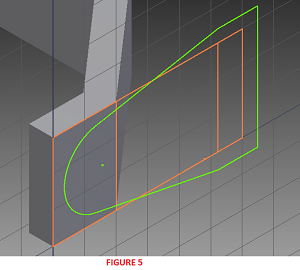
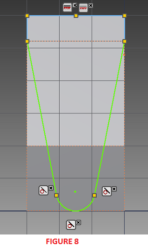
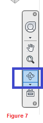
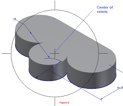
- Reorient the view to appear as shown in Figure 8. Use the ViewCube.
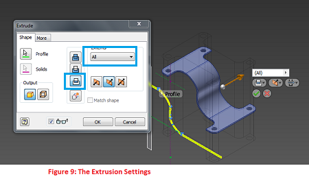
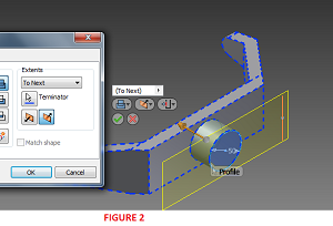
- Press E to launch the Extrude tool.
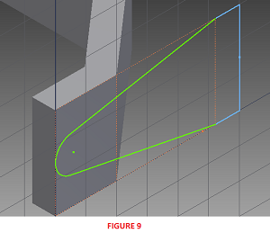
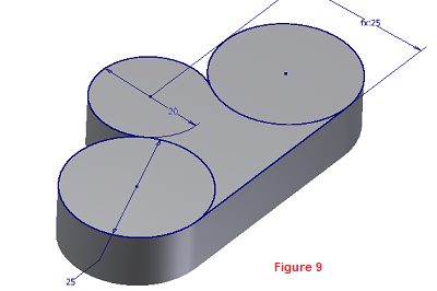
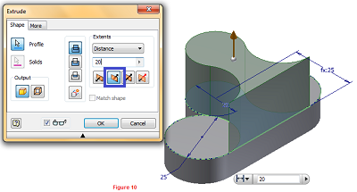
- On the Extrude dialog box, click on Intersect. Also select All on the Extents group. Refer to Figure 9.
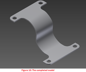
- Click OK to finish the extrusion.
- Click the visible work plane. Right click and click Visibility to make it invisible.
Now, you can appreciate the power of INTERSECTION. Go on and have fun. Think about any other crafty feature you could create with the INTERSECTION operation.