Pages

Other Menu

Minggu, 20 Juli 2014

Using the Fillet Tool ( Fillet Feature ) - Part 2

PLATFORM: AUTODESK INVENTOR PROFESSIONAL 2011/2012/2013
LEVEL OF DIFFICULTY: BEGINNERS
AUTHOR: NDIANABASI UDONKANG
FOLLOW ME ON: Twitter | Facebook | LinkedIn
This is a continuation of the series of lessons for new Inventor Users. Check out this blog's table-of-content page for more topics in this series

TOPIC: USING THE FILLET TOOL - part 2


BEFORE YOU BEGIN

  1. Download the dataset. The dataset files were created with Inventor 2011 to ensure compatibility with newer versions of Inventor.
  2. Save it to a project folder of an existing Inventor project. Set the project active. Learn more about Inventor Projects and Project Files.
  3. If there is any concept you do not understand, check out previous lesson: USING THE FILLET TOOL (FILLET FEATURE) - OVERVIEW.

INTRODUCTION

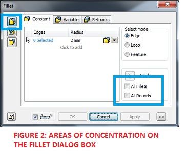
The Fillet tool can be used for creating various types of fillets/rounds. One of them is the constant-radius fillet. The constant-radius fillet applies only one radius at a time on any particular edge. To speed things up while creating fillets or rounds, we are going to learn how to use the All Fillets and All Rounds selection modes. The All Fillets mode allows you to select all interior edges on your part so that you can quickly apply fillets to them, while the All Round mode allows you to select all exterior edges on your part so that you can quickly apply rounds to them.

figure 2
This lesson is a sequel to USING THE FILLET TOOL (FILLET FEATURE) - OVERVIEW. Endeavour to read it before continuing here.

OBJECTIVES

At the end of this lesson, the reader should be able to:
  1. Describe and create a constant-radius edge fillet,
  2. Describe and create an edge fillet using the All Fillets selection mode,
  3. Describe and create an edge fillet using the All Round selection mode.

LOCATING THE FILLET TOOL

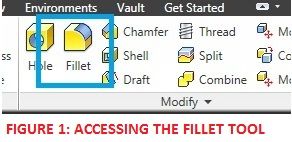
The Fillet tool could be found on:
  1. RIBBON: Model tab > Modify panel > Fillet

  2. SHORTCUT: F
procedures for creating a constant-radius fillet
In this section, we are going to learn how to create a constant-radius fillet.
  1. Open the dataset file, constant_radius_fillet.ipt
  2. Press F on your keyboard to launch the fillet tool. The Fillet dialog box is displayed (see Figure 3).

    Figure 4
  3. We are going to round all the edges on the top face of the part. On the Fillet dialog box > Constant tab and under Radius column, click 2mm. Type 20mm and press Enter. This sets 20mm as the new fillet radius.
  4. Now click on all the edges on the top face of the part, one after the other. You model should resemble the Figure 5 below. The dialog box (see Figure 4) indicates that 6 edges have been selected.

    Figure

    Figure
  5. Click OK to create the Fillet (see Figure 6).

    FIGURE 6
ALTERNATIVE METHOD
This is an alternative and faster method to the one above.
  1. Launch the Fillet tool.
  2. On the Fillet dialog box, set the radius to 20mm.
  3. On the right-hand side of the Fillet dialob box, set the Select Mode to "Loop."
  4. Point at one of edges on the top face, and ensure that it highlights the top face. When the top face is highlighted, click.
  5. Press OK to create the fillet.


REFERENCE
1. Autodesk Inventor 2010: Official Training Courseware.
I hope you learnt a lot from this lesson. If you have any questions, please drop a comment, and I will answer ASAP. Thank you.

Navigation in Autodesk Inventor - The SteeringWheel Tool


INTRODUCTION

Navigation in Autodesk Inventor embodies those operations carried out in order to view the model from different positions, directions (or orientations) and perspectives. When you navigate around your model, the position and orientation of the model with respect to the user-coordinate system is not altered.
Autodesk Inventor contains very interesting tools that allows you to have complete control of how your model is viewed and positioned in your Graphics Area.
The SteeringWheel is a User-Interface tool that brings together all your basic navigation tools ( Pan, Zoom and Orbit) and even more tools like Walk, Up/Down, Look, Rewind, and Center. The SteeringWheel provides easily access to all your navigation tools just around your mouse. When activated, the SteeringWheel is attached to the mouse.

OBJECTIVES

At the end of this lesson, the reader should be able:
  1. Explain the concept of navigation in Autodesk Inventor.
  2. Explain the functions of the SteeringWheel tool.
  3. Use the SteeringWheel for PANNING.
  4. Use the SteeringWheel for ZOOMING.
  5. Use the SteeringWheel for ORBITING.
  6. Use the SteeringWheel for REWINDING through previous views of the model.

LOCATING THE STEERINGWHEEL

The SteeringWheel can be located on the following places:
  1. RIBBON: View tab > Navigation panel > Full Navigation Wheel

    Locating the SteeringWheel

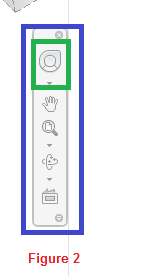
  2. NAVIGATION BAR

    Locating the SteeringWheel on the Nav Bar

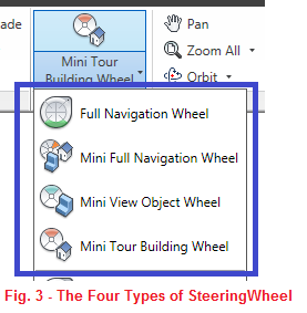
TYPES OF STEERINGWHEEL

Figure 3
There are four types of SteeringWheel in Autodesk Inventor, namely:
  1. Full Navigation Wheel,
  2. Mini Full Navigation Wheel,
  3. Mini View Object Wheel, and
  4. Mini Tour Building Wheel.

FULL NAVIGATION WHEEL

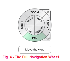
Figure 4
The Full Navigation Wheel is the big and complete version of the SteeringWheel, and by far the most widely used. As shown in Figure 4, it consists of the eight (8) tools, namely: ZOOM, ORBIT, PAN, REWIND, LOOK, CENTER, WALK, AND UP/DOWN tools.

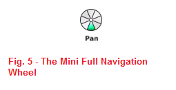
MINI FULL NAVIGATION WHEEL

Figure 3
The Mini Full Navigation Wheel contains all the tools found on the Full Navigation Wheel, however, it is reduced to a very small circular tool. You can switch between the tools by slightly rotating the mouse around the mini navigation wheel.

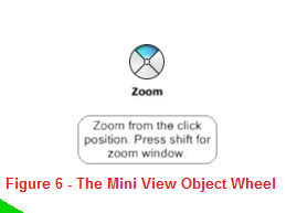
MINI VIEW OBJECT WHEEL

Figure 6
The Mini View Object Wheel displays those common navigation tools that are used to view objects in your model. The tools found on the Mini View Object Wheel include ZOOM, PAN, ORBIT, and REWIND.

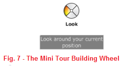
MINI TOUR BUILDING WHEEL

The Mini Tour Building Wheel displays the navigation tools that can aid in navigating around large models/ designs, for example, plant design (with large vessels, frames, and pipes) that was done with Inventor Professional. The tools found on the Mini Tour Building Wheel include LOOK, WALK, REWIND, and UP/DOWN.
Figure 7

NAVIGATING WITH THE STEERINGWHEEL

Navigating with the SteeringWheel is very simple and intuitive. Any of the tool on the SteeringWheel can be executed by clicking and holding the left button of a mouse. The functions of the ZOOM, PAN, and ORBIT tools worked just the same way as it works when executed by other methods. Learn more by following the links below:
One other important tool on the SteeringWheel is the REWIND tool. The REWIND tool allows you to step backwards (or rewind) through the previous views of your models. The steps are display like video frames (or thumbnails) so that you can use your mouse to move to the particular thumbnail you wish to go back to. Releasing the mouse at that thumbnail takes you back to that previous view. As you navigate around your model, the previous views are saved to the navigation history. The REWIND tool allows you to retrieve this navigation history.

I hope you learnt a lot from this lesson. If you have any questions, please drop a comment, and I will answer ASAP. Thank you.

Direct Manipulation in Autodesk Inventor


Direct Manipulation in Autodesk Inventor

INTRODUCTION

Direct Manipulation is a new modelling workflow that was introduced in Autodesk Inventor 2011. Direction Manipulation provides mini-toolbars and manipulators, as well as dynamic real-time feature previews, which provide efficient, predictable, and rich interaction. Efficiency is improved because the need to leave the graphics area to interact with the ribbon, dialog boxes, and browser is significantly reduced. Efficiency is further improved because dynamic accurate feature previews remove the guesswork from feature definition. Direct Manipulation improves the overall ease of use in your part modelling workflows.
Direct Manipulation is object-oriented. You interact directly with features in the canvas. You use it when you create and edit features.

OBJECTIVES

At the end of this lesson, the reader should be able:
  1. Describe the purpose of Direct Manipulation.
  2. Describe the various components of Direct Manipulation.
  3. Use Direct Manipulation for feature definition and creation.
  4. Use Direct Manipulation for feature editing.

COMPONENTS FOUND IN DIRECT MANIPULATION

There are various tools and features found in Direct Manipulation. They include:
  1. The In-Canvas Display,
  2. Manipulators,
  3. Mini-toolbars,
  4. Selection tags,
  5. Value input box, and
  6. Dynamic previews.
These tools are contextually available in the graphics window, and are directly, proximally associated with the feature to which you specify focus. Direct Manipulation has been added to Extrude, Fillet, Chamfer, Revolve, Hole, and Work features.

THE IN-CANVAS DISPLAY

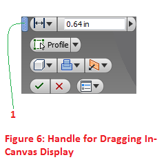
The in-canvas display is a user interface that is overlaid on the graphics window to support Direct Manipulation operations. It typically contains a mini-toolbar featuring command options, manipulators, a value input box, and selection tags. The mini-toolbar enables direct and predictable interaction with the 3D model. OK and Cancel buttons are located at the bottom of the in-canvas display to confirm or cancel an operation.
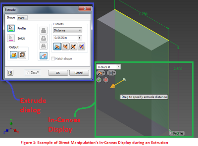
The In-Canvas Display
The in-canvas display can be relocated to any part of the graphics window by simply clicking and dragging it to any desire location (See Figure 6).
handle for relocating in-canvas display

MANIPULATORS

Manipulators are in-canvas interactive objects that enable the user to easily manipulate objects for various modeling and editing tasks.
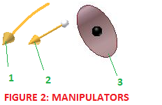
MANIPULATOR
:There are three types of manipulators in Direct Manipulation, namely:
  1. Rotational Arrow Manipulator,
  2. Distance Arrow Manipulator, and
  3. Sphere Manipulator.

  • The rotational arrow manipulator is used for dynamically revolving 2D profiles around a single axis, or to rotate a work plane around an edge.
  • The distance arrow manipulator is used for dynamically dragging the extrusion distance of one or more 2D profiles, or dragging the distance of an offset parallel work plane.
  • The sphere manipulator is used for locating the center of a hole, or for adjusting the taper angle of an extrusion.

MINI-TOOLBARS

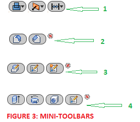
The mini-toolbars display in-canvas buttons that provide quick access to frequently used commands and command options. They are located in close proximity to a selected object in the graphics window. Button flyouts display command options where appropriate. (See Figure 3, Toolbar 1)
When an edge is selected, the mini-toolbar displays Fillet and Chamfer command buttons. A Cancel button is also displayed. (See Figure 3: Toolbar 2)
When a face is selected, the mini-toolbar displays command buttons to perform Edit Feature, Edit Sketch, or Create Sketch operations. A Cancel button is also displayed. (See Figure 3: Toolbar 3)
When a sketch is selected, the mini-toolbar displays Extrude, Revolve, Hole, and Edit Sketch command buttons. A Cancel button is also displayed. (See Figure 3: Toolbar 4)
mini-toolbars

SELECTION TAGS

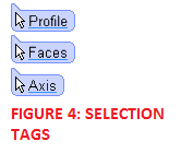
Selection tags are labels that appear in the in-canvas display and prompt for the selection of profiles, faces, and axes for feature creation and editing.
SELECTION TAGS
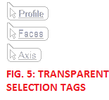
Once a profile, face, or axis has been selected, selection tags assume a nearly transparent appearance to indicate that the selection has been satisfied.
FIGURE 5: TRANSPARENT SELECTION TAGS
If you wish to return to profile selection mode, simply click on the Profile Selection tag and then add or remove the desire profiles. This process works for face selection and axis selection.

VALUE INPUT BOX

The value input box is used to enter numeric values for modeling and editing operations.While a manipulator is in use, the value input box updates in real time to show you the value of the parameter being manipulated. You could quickly enter the parameter value into the Value Input Box or right click to lookup a parameter from the parameter table of the current file. It is located just above the mini-toolbar in the in-canvas display.
VALUE INPUT BOX

DYNAMIC PREVIEWS

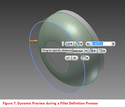
Dynamic Previews is fully integrated in Direct Manipulation. With dynamic preview, you can see real-time previews of your designs for various parameters during the feature definition process. This saves you the stress of guess work during feature definition and creation. While dragging the manipulators, dynamic preview actively shows you how your design will look for the current parameters settings.
dynamic previews

EXTRUDING WITH DIRECT MANIPULATION

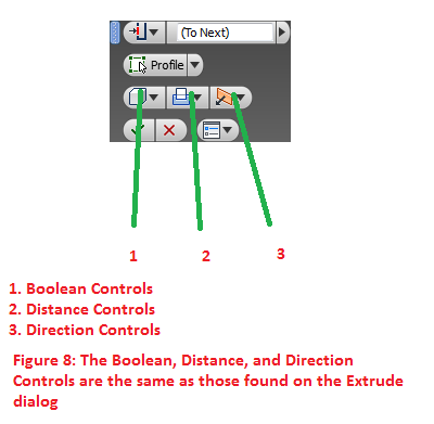
For Extrude, the most commonly used controls are replicated from the dialog box to the graphics window. Drag the distance arrow to change the extrude distance and extrude direction. This feature is particularly useful when you want to preview various extrude distances rapidly. Enter a value in the value input box to specify an exact distance. Use the Profile selection tag to return to profile selection mode after you use the manipulator or the value input box. As always, use the Ctrl key to add or remove profiles.
The Boolean, Direction, and Distance controls function the same as previous versions of Inventor.
extrude controls
The sphere manipulator is used to specify a taper for the extrusion.

OTHER NOTES ABOUT DIRECT MANIPULATION

You can access features directly in the graphics window. For example, select and edge and a mini-toolbar appears with tools relevant for manipulating the edge. If the preview option is selected in the dialog box, the dynamic preview provides real-time feedback.
When you select a feature e.g fillet, Direct Manipulation allows you to quickly edit the fillet by clicking on the mini-toolbar and changing the fillet radius using the manipulator or the input box.
When you select a sketch. You can use the mini-toolbar to edit, extrude, revolve, or use the sketch for hole placement.
Direct Manipulation for revolved features is very similar to extruded features. Drag the rotational arrow manipulator to preview the revolve.
Holes also use a manipulator and real-time preview. Drag the sphere manipulator to preview placement. When you enter values for reference distances, the padlock icon becomes active, indicating the value is locked in that direction. Click the icon to unlock and enter another value or drag the sphere manipulator. Other controls and specifications are in the dialog box, as in previous releases.
Direct Manipulation has also been applied to work features. When you specify a work plane through an edge, at an angle to a face, a rotational manipulator is attached to the work plane preview. Select a work plane and use the mini-toolbar to edit the offset distance or start a sketch.
References:
  1. Autodesk Inventor 2011 Help System.


I hope you learnt a lot from this lesson. If you have any questions, please drop a comment, and I will answer ASAP. Thank you.

Boolean Operations in Autodesk Inventor

Boolean Operations in Autodesk Inventor
BEFORE YOU BEGIN
  1. Download the dataset. The dataset files were created with Inventor 2011 to ensure compatibility with newer versions of Inventor.
  2. Extract the zipped file, and save the contents to a project folder of an existing Inventor project. Set the project active. Learn more about Inventor Projects and Project Files.
  3. Take some time and familiarise yourself with Direct Manipulation in Autodesk Inventor. Check out this lesson: Direct Manipulation in Autodesk Inventor.

INTRODUCTION

A typical solid part is often made up of numerous features that are craftily combined to form the model. When, you are creating such a model in a CAD application like Inventor or AutoCAD, you have to split the modelling operation into various stages. A good designer should be able to quickly determine the feature that should be created first, and those that should be created subsequently. The subsequent features would be combined with the first feature (usually called the base feature) with the help of join, cut, or intersect operations. These are the Boolean Operations in Autodesk Inventor: JOIN, CUT, and INTERSECT. The Boolean Operations are found in the Extrude, Revolve, Loft, and Sweep tools.

OBJECTIVES

At the end of this lesson, the reader should be able:
  1. Describe the reason for the using boolean operations in your design workflow,
  2. Describe the three basic boolean operations used in Autodesk Inventor,
  3. Create simple models using these boolean operations.

JOIN OPERATION

The JOIN operation is used for joining a sketched solid feature to an existing solid feature. The result is a bigger solid that consists of all the volume enclosed by the newly formed sketched feature and the existing solid. In simpler terms, use the JOIN operation to add more features to your base feature.
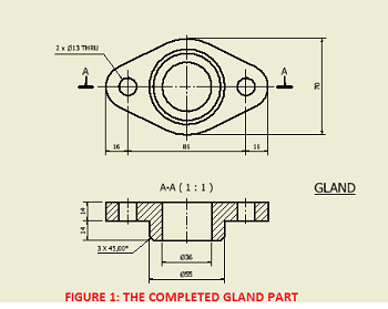
FIGURE 1
Let's have some fun, by creating the Gland part shown above.
BASE FEATURE
We are going to start by creating the base of the Gland part. The dataset file already contains the base sketch for the Gland.
  1. Open the file Gland.ipt from the extracted zipped file.
  2. Press F6 to set the view to the Home view.
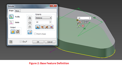
  3. Press "E" on your keyboard to launch the Extrude tool (or go to Model tab > Create panel > Extrude tool on your Ribbon).
  4. Set the Extrusion distance to 14mm and click OK or the green tick mark.
Figure 2
CREATING A NEW SKETCH USING A PLANAR FACE
Now, we are going to create a new sketch on the top face of our base feature.
Figure 3
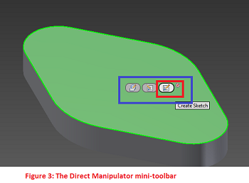
  1. Click the top of the base feature. The Direct-Manipulation mini-toolbar is display. Click Create Sketch.
  2. Press Page Up and click the top of the base feature to Look At the new sketch.
  3. In the Sketch environment, press C to launch the Circle tool. Click the centerpoint of the sketch as the center of the circle.
  4. Type 55 as the diameter of the circle, and press the Enter key.
  5. Press F6 to view the sketch in the Home view. Press E to launch the Extrude tool.
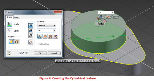
  6. To select your extrusion profile, click inside the 55-mm diameter circle. Use 14mm as the extrusion distance. Leave other settings as they are. Use Figure 4 as your reference.
  7. Click OK to finish the feature.
Figure 4
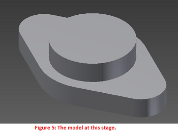
Figure 5

CUT OPERATION

The CUT operation is used for cutting a sketched feature from an existing solid feature. The result is a new solid that encloses the volume enclosed by the original solid but not by the newly formed sketched feature. In other words, the CUT operation subtracts the volume defined by the new sketched feature from that of the original sketched feature.
Let's demonstrate this by creating a hole from the center of our Gland part.
  1. Click on the top face of the newly-created cylindrical feature. Click Create Sketch.
  2. Press Page Up and select the top face of the cylinder to Look At the Sketch. Press C to launch the Circle tool.
  3. Click the center of the sketch as the center of the circle, and type 36 as the diameter of the new circle.
  4. Press F6 to return to the Home view. Press E to launch the Extrude tool.
  5. Click within the 36-mm circle as the profile.
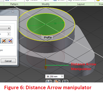
  6. Click the Distance Arrow manipulator and drag it downwards, making it cut through the solid model (See Figure 6).
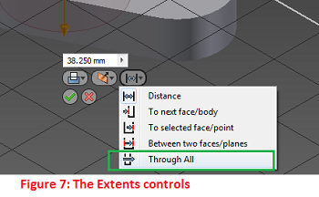
  7. Go to the In-Canvas Display > Extents control > Select Through All.
  8. Click OK.
  9. Go on and add other features. Have fun.
Figure 6
Figure 7
Points to Note:
  1. By clicking and dragging the manipulator through the existing solid, the system changes the boolean mode from Join to Cut. Drag the manipulator above and through the model and observe the subtle changes in the Extrude dialog box.
  2. You could explicitly specify the Cut operation by clicking Cut on the Extrude dialog or via the In-Canvas display.

INTERSECT OPERATION

The INTERSECT operation creates a new feature or solid by retaining the volume common to the existing sketched feature and the newly formed sketched feature.
Let us create an interesting design using the INTERSECT operation.
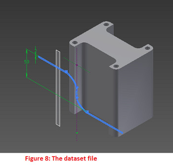
  1. Open the file DataSet_Intersection.ipt. The file contains an extruded feature and an unconsumed sketch.
  2. Reorient the view to appear as shown in Figure 8. Use the ViewCube.
  3. Press E to launch the Extrude tool.
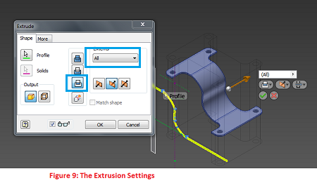
  4. On the Extrude dialog box, click on Intersect. Also select All on the Extents group. Refer to Figure 9.
  5. Click OK to finish the extrusion.
  6. Click the visible work plane. Right click and click Visibility to make it invisible.
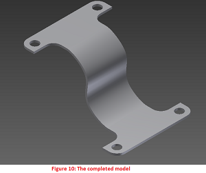
Now, you can appreciate the power of INTERSECTION. Go on and have fun. Think about any other crafty feature you could create with the INTERSECTION operation.
Figure 8
Figure 9
Figure 10

I hope you learnt a lot from this lesson. If you have any questions, please drop a comment, and I will answer ASAP. Thank you.

Using the Revolve Tool (Revolution Feature)

 Using the Revolve Tool (Revolution Feature)
PLATFORM: AUTODESK INVENTOR PROFESSIONAL 2011/2012/2013
LEVEL OF DIFFICULTY: BEGINNERS
AUTHOR: NDIANABASI UDONKANG
FOLLOW ME ON: Twitter | Facebook | LinkedIn
This is a continuation of the series of lessons for new Inventor Users. Check out this blog's table-of-content page for more topics in this series

TOPIC: USING THE REVOLVE TOOL (REVOLUTION FEATURE)


BEFORE YOU BEGIN

  1. Download the dataset. The dataset files were created with Inventor 2011 to ensure compatibility with newer versions of Inventor.
  2. Extract the content using any unzipping utility.
  3. Save the files to a project folder of an existing Inventor project. Set the project active. Learn more about Inventor Projects and Project Files.
  4. Go through the tutorial: Understand and Using Sketch Linetypes and Geometry in Autodesk Inventor. It will help you understand terms like normal geometry, centerline geometry and construction geometry.

INTRODUCTION

Revolution is the process of sweeping a profile around a center axis. Revolution is used for creating parts that will be machined out through turning on a lathe machine. Such parts usually consists of circular features arranged around a common axis.
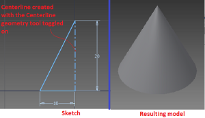
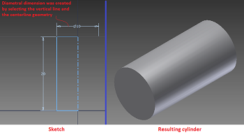
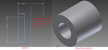
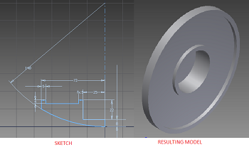
In Autodesk Inventor, a revolution feature is created using the Revolve tool. Table 1 shows examples of 2D sketches and the resulting models after a revolution operation. When creating a sketch that would be used for revolution, some facts have to be put into consideration. These include:
  1. Imagine that the part to be created is sectioned longitudinally (that is, along its axis).
  2. Sketch out the quarter-section of the part.
  3. Draw a center line that represents the longitudinal axis of the part.
  4. The center line should be drawn with the Centerline geometry settings toggled on.
  5. When creating dimensions, dimension between the centerline and any other sketch geometry. This will create a diameter dimension that shows you the actual diametric dimension of the part.
It is also important to know when to use Revolve tool for creating circular features and when to use the Extrude tool for creating cylindrical features.
  1. If you are creating a step shaft (that is, a shaft with varying cross-sectional areas along its longitudinal axis), then you should use the Revolve tool. This way, you will have an overview of the contour of the shaft from the beginning. You could easy make changes to the shaft profile just in one sketch.
  2. If you are creating a simple shaft with a constant cross-sectional area, then it is very efficient to use the Extrude tool to create a cylinder feature that represents the shaft.
  3. If you are creating a delicate circular model like a table-water bottle, then the Revolve tool will be the best tool to use. But your sketch must reflect all the delicate curves and grooves commonly found on such consumer products.
# Sketch Geometry Sketch and Resulting Model
1. Triangular Sketch triangular sketch and conical feature
2. Rectangular sketch rectangular sketch and resulting cylinder
3. Rectangular sketch (with a gap between the profile and the axis)
4. Any other profile.
Table 1: A table Showing Different Sketches and Resulting Revolution Features

OBJECTIVES

At the end of this lesson, the reader should be able:
  1. Explain the principle behind the creation of revolved features using the Revolution.
  2. Use the Revolve tool for creating an Revolution Features.
  3. Use the centerline geometry for defining the axis of revolution.

LOCATING THE REVOLVE TOOL

The Revolve tool could be found on:
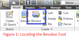
  1. RIBBON: Model tab > Create panel > Revolve

    figure 1

  2. SHORTCUT: When you are in the Sketch environment and are through with the necessary sketches, simply press "R" on your keyboard to launch the Revolve tool.
With no further ado, let's get started. We are going to create a lot of revolved models, in order to enhance the understanding of the tool.
The dataset files contain base sketches for the models we are about to create. You could quickly use them for the exercises or create your own sketches from the scratch.
creating a centerline geometry
When you are creating a sketch that is meant to be revolved, it is advisable to uniquely define a line that will be used as the axis of revolution. This is often done by creating a line with a centerline geometry property. However, Inventor will works perfectly well with a line created with the normal geometry property. The difference is that when you explicitly define a single centerline in your sketch, Inventor will automatically recognise and select that centerline when you launch the Revolve tool. This way, your design intent is established right from the sketch and you will not pass through the hassle of selecting the axis of revolution when the Revolve dialog box comes on!
In case you are not familiar with the types of geometry in Autodesk Inventor, read this lesson: Understand and Using Sketch Linetypes and Geometry in Autodesk Inventor.
You can create a centerline geometry in two ways:
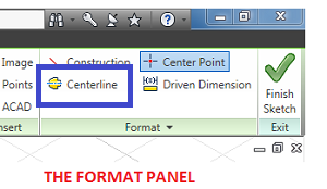
  1. FROM AN EXISTING NORMAL GEOMETRY. In this method, you create the centerline as a normal geometry in the sketch environment. (Normal geometry are continuous, and are color-coded green when not fully constrained and navy blue when fully constrained.) After creating the normal geometry, click to select it. Go to the Format panel and click Centerline. This will toggle on Centerline for that particular geometry and effectively converts it to Centerline geometry.
  2. DURING SKETCH GEOMETRY CREATION. In this method, you, first of all, go to the Format panel and toggle on the Centerline tool. Then go on and create the geometry as required. Inventor will create a centerline geometry. When you are through with creating the centerline, go back to the Format panel and toggle off the Centerline tool. I do not have to tell what will happen if the Centerline tool is not toggled off!
FORMAT PANEL

MODELLING A wheel CAP

In this exercise, we are going model a wheel cap for an infant scooter.
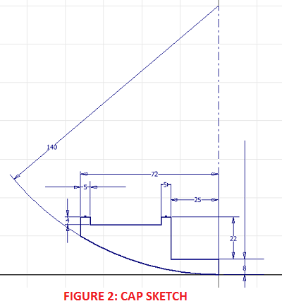
  1. Open the dataset file using_revolve_tool-CAP.ipt. If you want to create the sketch yourself, refer to Figure 2 for the sketch.

    figure 2
  2. Take some time to study the sketch. Take note of the normal geometry used for the profile that is to be revolved. Also take note of the centerline geometry, which will be used as the axis of revolution.
  3. With the file opened, press "R" on your keyboard, or click Revolve on the Model tab > Create panel.
  4. Inventor immediately selected the closed profile and the centerline, and displays a preview. Click OK to finish the revolution.
  5. Orbit or change the view using the viewcube to see the other side of the model.
MODELLING AN INFANT-SCOOTER WHEEL
Let us create another revolved model. In this exercise, we are going model a wheel for an infant scooter.
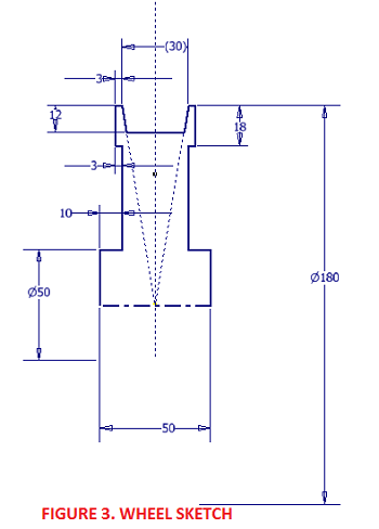
  1. Open the dataset file using_revolve_tool-WHEEL.ipt. If you want to create the sketch yourself, refer to Figure 3 for the sketch.

    WHEEL SKETCH
  2. Take note of normal geometry, construction geometry, and centerline geometry used in the sketch. Also take note of the diametric dimension created between the centerline geometry and two of the normal linetype entities.
  3. With the file opened, press "R" on your keyboard, or click Revolve on the Model tab > Create panel.
  4. Inventor immediately selected the closed profile and the centerline, and displays a preview. Click OK to finish the revolution.
  5. Orbit or change the view using the viewcube to see the other side of the model.
USING THE REVOLVE TOOL TO REMOVE A PORTION OF A MODEL
Just like the Extrude tool, we can use boolean operations (Join, Cut, Intersect) with the Revolve tool.
APPLICATION & DOCUMENT OPTIONS
Before we begin, let's customise our application and document:
  1. Go to Tools tab > Options panel > click Application Options.
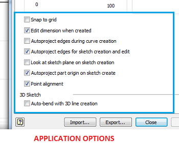
  2. On the Application Options dialog box, click on the Sketch tab.
  3. Ensure that the lower section of sketch settings are as shown in the image below. Click Ok to exit.

    application options
  4. Go to Tools tab > Options panel > click Document Options.
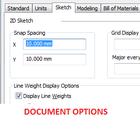
  5. On the Documents Options dialog box, click on the Sketch tab.
  6. Set the X & Y Snap Spacing to 10mm. Click Ok to exit.
    DOCUMENT OPTIONS
BASE SKETCH & BASE FEATURE
You could jump-start by opening using_revolve_tool-GROOVE-sketch1.ipt. Or you could follow the steps below:
  1. Create a new part file using the template Standard (mm).ipt.
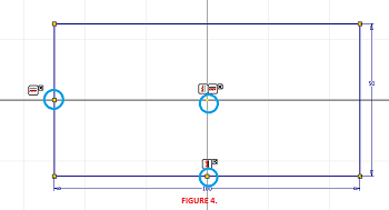
  2. Create the sketch shown in Figure 4.
  3. Make sure that the rectangle is centered around the Origin of the Sketch. Do the following:
    1. Ensure that you are looking at the sketch. Press "Page Up" on your keyboard and click Sketch1 on the Browser to Look At your sketch.
    2. On the sketch environment, go the Constraint panel > Horizontal constraint.
    3. Click the midpoint of the left vertical line and then click the sketch origin.
    4. On the Constraint panel, launch the Vertical constraint tool.
    5. Click the midpoint of the bottom horizontal line and then click the sketch origin.

  4. figure 4
  5. Press "S" on your keyboard, or click Finish Sketch to exit the Sketch environment.
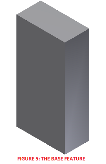
  6. Press "E" on your keyboard to launch the Extrude tool. Set the distance to 200mm. Click OK to create the extrusion. Double click the mouse wheel to Zoom Extents. See Figure 5 for the base feature.
    FIGURE 5
SECOND SKETCH & GROOVE
You could jump-start by opening using_revolve_tool-GROOVE-sketch2.ipt. Or you could continue with the steps below:
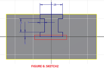
  1. Right click on the top face of the base feature. Click New Sketch on the shortcut menu. Press "Page Up" on your keyboard and click Sketch2 on your Browser.
  2. Create the sketch shown in Figure 6. Apply geometric constraints like symmetric and collinear to reduce the number of dimensions required to stabilise the sketch. Make sure the bottom line of the sketch passes through the sketch origin (as highlighted in Figure 6).

    figure 6
  3. Select the four reference geometry that were auto-projected on sketch creation. Click Construction on the Format panel. This converts the reference geometry to reference construction geometry.
  4. Select the vertical line passing through the center of the sketch. Convert it to a construction geometry.
  5. Press "S" on your keyboard to exit the sketch environment. Your sketch is ready.
  6. Press "E" to launch the Extrude tool. Set the Boolean operation to Cut and Extents Distance to 150mm. Click Ok to create the extrusion.
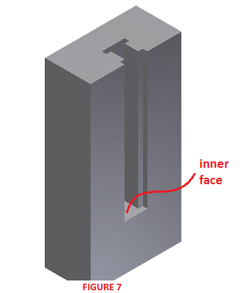
  7. Orient the model using the viewcube the orientation shown in Figure 7.

    FIGURE 7
THIRD SKETCH AND REVOLVED GROOVE
You could jump-start by opening using_revolve_tool-GROOVE-sketch3.ipt. Or you could continue with the steps below:
  1. Click on the inner face of the groove (highlighted in Figure 7). Right click and select New Sketch on the shortcut menu.
  2. Press "Page Up" on your keyboard and click on Sketch3 on your Browser. Press "F7" on your keyboard to slice the sketch.
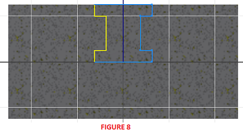
  3. Refer to Figure 8 and select the 7 reference geometry shown in light blue. Convert them to construction geometry.
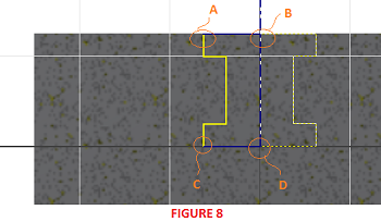
  4. Draw a vertical line passing through the center of the sketch. Use the midpoint of the bottom horizontal line as the start point. Convert it to a centerline geometry (See Figure 8).

    figure 8
  5. Now draw two normal lines from point A to B and from point C to D as shown in Figure 9. These two lines will help in closing the sketch, else we won't be able to create a solid revolution.

    FIGURE 9
  6. Press "F6" to view the sketch in the Home View.
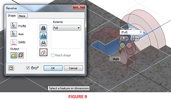
  7. Press "R" to launch Revolve tool. Set the Boolean options to Cut and leave the Extents at Full. See Figure 9.

    figure 9
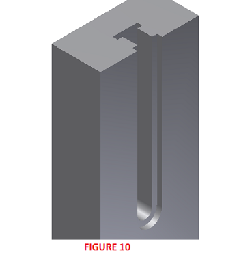
  8. Click Ok to create the revolution. See Figure 10.

    figure 10
  9. Compare your result with using_revolve_tool-GROOVE-completed.ipt.
This is the end of a long tutorial. I took tremendous time to develop the tutorial so that new users could follow up. If you did not understand some concepts, please refer to the Table of Contents page for other introductory lessons. Cheers!

I hope you learnt a lot from this lesson. If you have any questions, please drop a comment, and I will answer ASAP. Thank you.