Using the Extrude Tool (Extrusion Feature) - Part II-->
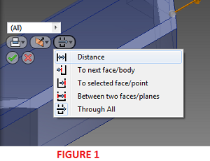
DISTANCE
The distance option extrudes in one direction only. It is the default option for creating extrusions in Inventor. With this option, the extrusion distance is simply typed into the value input box. One can combine the distance option with the direction controls (Direction 1, Direction 2, Symmetric, and Asymmetric) to achieve the desire extrusion. Most of the extrusion done in the first part of this lesson were carried out using the Distance option.
TO NEXT BODY/FACE
This option is used when the extrusion is desired to terminate at the next possible face or plane in the specified direction. This option is not available for base features or assembly extrusions.
TO SELECTED FACE/POINT
Part Environment: When you choose To Selected Face/Point, next, select an ending point, vertex, face, or plane on which to terminate the extrusion. For points and vertices, the extrusion will be terminated on a plane parallel to the sketch plane which passes through the selected point or vertex. For faces or planes, the extrusion will be terminated on the selected face, or on a face that extends beyond the termination plane.
Assembly Environment: For assembly extrusions, sketch points, vertices, faces, and planes that reside on other components can be selected. Work planes and work points must reside on the same assembly level as the assembly extrusion being created to be selected.
If you terminate the extrusion on a face or plane, use options on the More tab to indicate a more specific solution when termination options are ambiguous, such as on a cylinder or irregular surface. On the More tab, Alternate Solution flips direction, selecting the termination face at the maximum distance. Select Minimum Solution to terminate on the first encountered face.
BETWEEN TWO FACES/PLANES
Part Environment: For part extrusions, selects beginning and ending faces or planes on which to terminate the extrusion.
Assembly Environment: For assembly extrusions, selects a face or plane on which to terminate the extrusion. Faces and planes that reside on other components can be selected. The selected faces or planes must reside on the same assembly level as the assembly extrusion being created. Not available for base features.
After you select the start and termination planes, use options on the More tab to indicate a more specific solution when termination options are ambiguous, such as on a cylinder or irregular surface. On the More tab, Alternate Solution flips direction, selecting the termination face at the maximum distance. Select Minimum Solution to terminate on the first encountered face.
THROUGH ALL
The Through All option is used to extrude the profile through all features and sketches in the specified direction. We have demonstrated this option in previous lessons.
REFERENCES
PLATFORM: AUTODESK INVENTOR PROFESSIONAL 2011/2012/2013
LEVEL OF DIFFICULTY: BEGINNERS
AUTHOR: NDIANABASI UDONKANG
This is a continuation of the series of lessons for new Inventor Users. Check out this blog's table-of-content page for more topics in this series
TOPIC: USING THE EXTRUDE TOOL (EXTRUSION FEATURE) - PART II
BEFORE YOU BEGIN
- Download the dataset. The dataset files were created with Inventor 2011 to ensure compatibility with newer versions of Inventor.
- Extract the content using any unzipping utility.
- Save the files to a project folder of an existing Inventor project. Set the project active. Learn more about Inventor Projects and Project Files.
INTRODUCTION
This is the continuation of the lesson "Using th Extrude Tool (Extrusion Feature)." In this lesson, we are going to explore other Extents options found in Extrude dialog box in Autodesk Inventor. An understanding of the uses of each of the Extents options is important especially when complex designs are being created.EXTENTS OPTIONS
The Extents options determine the methods for ending an extrusion and set its depth. Extrusions can be a specific depth or can terminate on a work plane, construction surface, or part face (including planar, cylindrical, spherical or toroidal face). The Extents options include:- Distance,
- To next face/body,
- To selected face/point,
- Between two faces/planes,
- Through All.

DISTANCE
The distance option extrudes in one direction only. It is the default option for creating extrusions in Inventor. With this option, the extrusion distance is simply typed into the value input box. One can combine the distance option with the direction controls (Direction 1, Direction 2, Symmetric, and Asymmetric) to achieve the desire extrusion. Most of the extrusion done in the first part of this lesson were carried out using the Distance option.
TO NEXT BODY/FACE
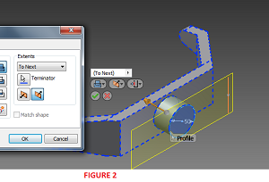
This option is used when the extrusion is desired to terminate at the next possible face or plane in the specified direction. This option is not available for base features or assembly extrusions.
- Open the file Front_Frame_Extrusion_Lesson 2.ipt. The model contains an unconsummed sketch.
- Re-orient the view as shown in Figure 2.
- Launch the Extrude tool and set the Extents to To Next Body/Face. Click OK.
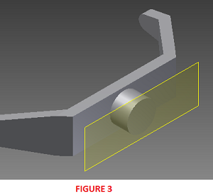
- The Resulting solid is shown in Figure 3.


TO SELECTED FACE/POINT
Part Environment: When you choose To Selected Face/Point, next, select an ending point, vertex, face, or plane on which to terminate the extrusion. For points and vertices, the extrusion will be terminated on a plane parallel to the sketch plane which passes through the selected point or vertex. For faces or planes, the extrusion will be terminated on the selected face, or on a face that extends beyond the termination plane.
Assembly Environment: For assembly extrusions, sketch points, vertices, faces, and planes that reside on other components can be selected. Work planes and work points must reside on the same assembly level as the assembly extrusion being created to be selected.
If you terminate the extrusion on a face or plane, use options on the More tab to indicate a more specific solution when termination options are ambiguous, such as on a cylinder or irregular surface. On the More tab, Alternate Solution flips direction, selecting the termination face at the maximum distance. Select Minimum Solution to terminate on the first encountered face.
BETWEEN TWO FACES/PLANES
Part Environment: For part extrusions, selects beginning and ending faces or planes on which to terminate the extrusion.
Assembly Environment: For assembly extrusions, selects a face or plane on which to terminate the extrusion. Faces and planes that reside on other components can be selected. The selected faces or planes must reside on the same assembly level as the assembly extrusion being created. Not available for base features.
After you select the start and termination planes, use options on the More tab to indicate a more specific solution when termination options are ambiguous, such as on a cylinder or irregular surface. On the More tab, Alternate Solution flips direction, selecting the termination face at the maximum distance. Select Minimum Solution to terminate on the first encountered face.
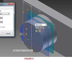
- Open the file Front_Frame_Extrusion_Lesson 3.ipt. The model contains an unconsummed sketch and two work planes.
- Launch the Extrude tool. Click inside the smaller chord as the extrusion profile. See Figure 4.
- For Extents, choose Between Two Faces/Planes.
- For Starting plane/face, select the inner work plane (shown in green in Figure 4).
- For Ending plane/face, select the outer work plane (shown in blue in Figure 4).
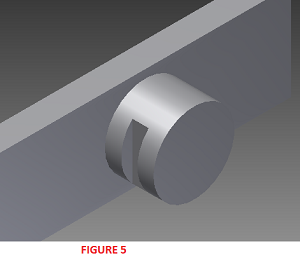
- Clik OK to finish. The completed feature is shown in Figure 5.


THROUGH ALL
The Through All option is used to extrude the profile through all features and sketches in the specified direction. We have demonstrated this option in previous lessons.
REFERENCES
- Autodesk Inventor 2011 Help System.
0 komentar:
Posting Komentar