Using the Revolve Tool (Revolution Feature)
In Autodesk Inventor, a revolution feature is created using the Revolve tool. Table 1 shows examples of 2D sketches and the resulting models after a revolution operation. When creating a sketch that would be used for revolution, some facts have to be put into consideration. These include:
The dataset files contain base sketches for the models we are about to create. You could quickly use them for the exercises or create your own sketches from the scratch.
PLATFORM: AUTODESK INVENTOR PROFESSIONAL 2011/2012/2013
LEVEL OF DIFFICULTY: BEGINNERS
AUTHOR: NDIANABASI UDONKANG
This is a continuation of the series of lessons for new Inventor Users. Check out this blog's table-of-content page for more topics in this series
TOPIC: USING THE REVOLVE TOOL (REVOLUTION FEATURE)
BEFORE YOU BEGIN
- Download the dataset. The dataset files were created with Inventor 2011 to ensure compatibility with newer versions of Inventor.
- Extract the content using any unzipping utility.
- Save the files to a project folder of an existing Inventor project. Set the project active. Learn more about Inventor Projects and Project Files.
- Go through the tutorial: Understand and Using Sketch Linetypes and Geometry in Autodesk Inventor. It will help you understand terms like normal geometry, centerline geometry and construction geometry.
INTRODUCTION
Revolution is the process of sweeping a profile around a center axis. Revolution is used for creating parts that will be machined out through turning on a lathe machine. Such parts usually consists of circular features arranged around a common axis.In Autodesk Inventor, a revolution feature is created using the Revolve tool. Table 1 shows examples of 2D sketches and the resulting models after a revolution operation. When creating a sketch that would be used for revolution, some facts have to be put into consideration. These include:
- Imagine that the part to be created is sectioned longitudinally (that is, along its axis).
- Sketch out the quarter-section of the part.
- Draw a center line that represents the longitudinal axis of the part.
- The center line should be drawn with the Centerline geometry settings toggled on.
- When creating dimensions, dimension between the centerline and any other sketch geometry. This will create a diameter dimension that shows you the actual diametric dimension of the part.
- If you are creating a step shaft (that is, a shaft with varying cross-sectional areas along its longitudinal axis), then you should use the Revolve tool. This way, you will have an overview of the contour of the shaft from the beginning. You could easy make changes to the shaft profile just in one sketch.
- If you are creating a simple shaft with a constant cross-sectional area, then it is very efficient to use the Extrude tool to create a cylinder feature that represents the shaft.
- If you are creating a delicate circular model like a table-water bottle, then the Revolve tool will be the best tool to use. But your sketch must reflect all the delicate curves and grooves commonly found on such consumer products.
| # | Sketch Geometry | Sketch and Resulting Model |
|---|---|---|
| 1. | Triangular Sketch | 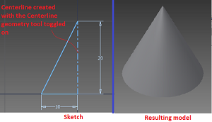 |
| 2. | Rectangular sketch | 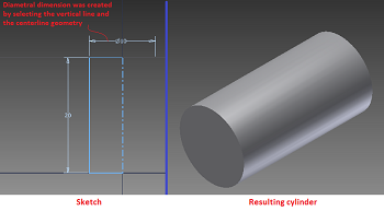 |
| 3. | Rectangular sketch (with a gap between the profile and the axis) | 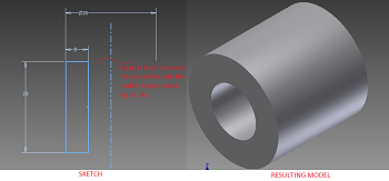 |
| 4. | Any other profile. | 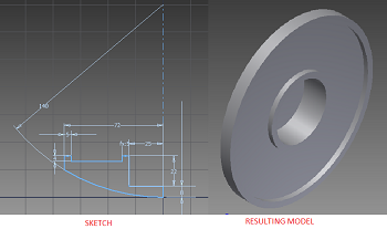 |
OBJECTIVES
At the end of this lesson, the reader should be able:- Explain the principle behind the creation of revolved features using the Revolution.
- Use the Revolve tool for creating an Revolution Features.
- Use the centerline geometry for defining the axis of revolution.
LOCATING THE REVOLVE TOOL
The Revolve tool could be found on:- RIBBON: Model tab > Create panel > Revolve
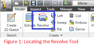
- SHORTCUT: When you are in the Sketch environment and are through with the necessary sketches, simply press "R" on your keyboard to launch the Revolve tool.
The dataset files contain base sketches for the models we are about to create. You could quickly use them for the exercises or create your own sketches from the scratch.
creating a centerline geometry
When you are creating a sketch that is meant to be revolved, it is advisable to uniquely define a line that will be used as the axis of revolution. This is often done by creating a line with a centerline geometry property. However, Inventor will works perfectly well with a line created with the normal geometry property. The difference is that when you explicitly define a single centerline in your sketch, Inventor will automatically recognise and select that centerline when you launch the Revolve tool. This way, your design intent is established right from the sketch and you will not pass through the hassle of selecting the axis of revolution when the Revolve dialog box comes on!
In case you are not familiar with the types of geometry in Autodesk Inventor, read this lesson: Understand and Using Sketch Linetypes and Geometry in Autodesk Inventor.
You can create a centerline geometry in two ways:
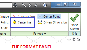
- FROM AN EXISTING NORMAL GEOMETRY. In this method, you create the centerline as a normal geometry in the sketch environment. (Normal geometry are continuous, and are color-coded green when not fully constrained and navy blue when fully constrained.) After creating the normal geometry, click to select it. Go to the Format panel and click Centerline. This will toggle on Centerline for that particular geometry and effectively converts it to Centerline geometry.
- DURING SKETCH GEOMETRY CREATION. In this method, you, first of all, go to the Format panel and toggle on the Centerline tool. Then go on and create the geometry as required. Inventor will create a centerline geometry. When you are through with creating the centerline, go back to the Format panel and toggle off the Centerline tool. I do not have to tell what will happen if the Centerline tool is not toggled off!

MODELLING A wheel CAP
In this exercise, we are going model a wheel cap for an infant scooter.- Open the dataset file using_revolve_tool-CAP.ipt. If you want to create the sketch yourself, refer to Figure 2 for the sketch.
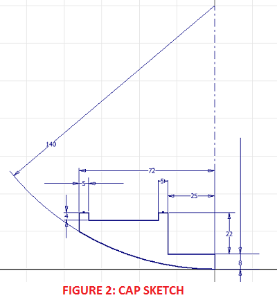
- Take some time to study the sketch. Take note of the normal geometry used for the profile that is to be revolved. Also take note of the centerline geometry, which will be used as the axis of revolution.
- With the file opened, press "R" on your keyboard, or click Revolve on the Model tab > Create panel.
- Inventor immediately selected the closed profile and the centerline, and displays a preview. Click OK to finish the revolution.
- Orbit or change the view using the viewcube to see the other side of the model.
MODELLING AN INFANT-SCOOTER WHEEL
Let us create another revolved model. In this exercise, we are going model a wheel for an infant scooter. - Open the dataset file using_revolve_tool-WHEEL.ipt. If you want to create the sketch yourself, refer to Figure 3 for the sketch.
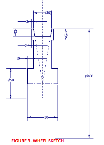
- Take note of normal geometry, construction geometry, and centerline geometry used in the sketch. Also take note of the diametric dimension created between the centerline geometry and two of the normal linetype entities.
- With the file opened, press "R" on your keyboard, or click Revolve on the Model tab > Create panel.
- Inventor immediately selected the closed profile and the centerline, and displays a preview. Click OK to finish the revolution.
- Orbit or change the view using the viewcube to see the other side of the model.
USING THE REVOLVE TOOL TO REMOVE A PORTION OF A MODEL
Just like the Extrude tool, we can use boolean operations (Join, Cut, Intersect) with the Revolve tool.
APPLICATION & DOCUMENT OPTIONS
Before we begin, let's customise our application and document:
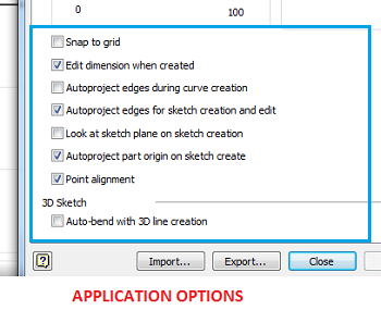
- Go to Tools tab > Options panel > click Application Options.
- On the Application Options dialog box, click on the Sketch tab.
- Ensure that the lower section of sketch settings are as shown in the image below. Click Ok to exit.
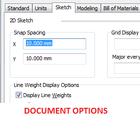
- Go to Tools tab > Options panel > click Document Options.
- On the Documents Options dialog box, click on the Sketch tab.
- Set the X & Y Snap Spacing to 10mm. Click Ok to exit.
BASE SKETCH & BASE FEATURE
You could jump-start by opening using_revolve_tool-GROOVE-sketch1.ipt. Or you could follow the steps below:- Create a new part file using the template Standard (mm).ipt.
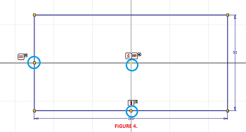
- Create the sketch shown in Figure 4.
- Make sure that the rectangle is centered around the Origin of the Sketch. Do the following:
- Ensure that you are looking at the sketch. Press "Page Up" on your keyboard and click Sketch1 on the Browser to Look At your sketch.
- On the sketch environment, go the Constraint panel > Horizontal constraint.
- Click the midpoint of the left vertical line and then click the sketch origin.
- On the Constraint panel, launch the Vertical constraint tool.
- Click the midpoint of the bottom horizontal line and then click the sketch origin.
- Press "S" on your keyboard, or click Finish Sketch to exit the Sketch environment.
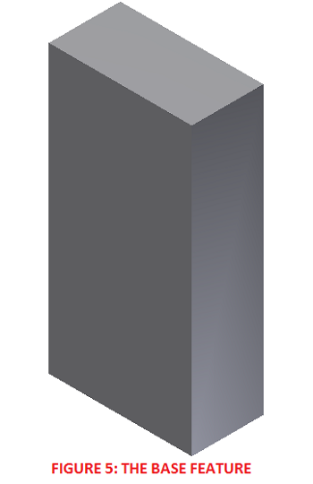
- Press "E" on your keyboard to launch the Extrude tool. Set the distance to 200mm. Click OK to create the extrusion. Double click the mouse wheel to Zoom Extents. See Figure 5 for the base feature.
SECOND SKETCH & GROOVE
You could jump-start by opening using_revolve_tool-GROOVE-sketch2.ipt. Or you could continue with the steps below:- Right click on the top face of the base feature. Click New Sketch on the shortcut menu. Press "Page Up" on your keyboard and click Sketch2 on your Browser.
- Create the sketch shown in Figure 6. Apply geometric constraints like symmetric and collinear to reduce the number of dimensions required to stabilise the sketch. Make sure the bottom line of the sketch passes through the sketch origin (as highlighted in Figure 6).
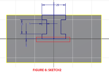
- Select the four reference geometry that were auto-projected on sketch creation. Click Construction on the Format panel. This converts the reference geometry to reference construction geometry.
- Select the vertical line passing through the center of the sketch. Convert it to a construction geometry.
- Press "S" on your keyboard to exit the sketch environment. Your sketch is ready.
- Press "E" to launch the Extrude tool. Set the Boolean operation to Cut and Extents Distance to 150mm. Click Ok to create the extrusion.
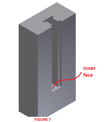
- Orient the model using the viewcube the orientation shown in Figure 7.
THIRD SKETCH AND REVOLVED GROOVE
You could jump-start by opening using_revolve_tool-GROOVE-sketch3.ipt. Or you could continue with the steps below:- Click on the inner face of the groove (highlighted in Figure 7). Right click and select New Sketch on the shortcut menu.
- Press "Page Up" on your keyboard and click on Sketch3 on your Browser. Press "F7" on your keyboard to slice the sketch.
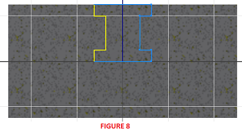
- Refer to Figure 8 and select the 7 reference geometry shown in light blue. Convert them to construction geometry.
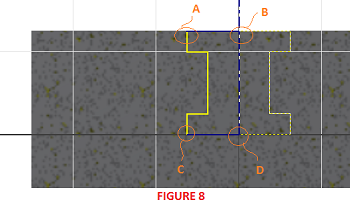
- Draw a vertical line passing through the center of the sketch. Use the midpoint of the bottom horizontal line as the start point. Convert it to a centerline geometry (See Figure 8).
- Now draw two normal lines from point A to B and from point C to D as shown in Figure 9. These two lines will help in closing the sketch, else we won't be able to create a solid revolution.
- Press "F6" to view the sketch in the Home View.
- Press "R" to launch Revolve tool. Set the Boolean options to Cut and leave the Extents at Full. See Figure 9.
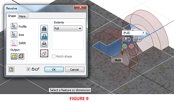
- Click Ok to create the revolution. See Figure 10.
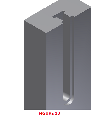
- Compare your result with using_revolve_tool-GROOVE-completed.ipt.
0 komentar:
Posting Komentar