Using the Extrude Tool (Extrusion Feature)-->
PLATFORM: AUTODESK INVENTOR PROFESSIONAL 2011/2012/2013
LEVEL OF DIFFICULTY: BEGINNERS
AUTHOR: NDIANABASI UDONKANG
This is a continuation of the series of lessons for new Inventor Users. Check out this blog's table-of-content page for more topics in this series
TOPIC: USING THE EXTRUDE TOOL (EXTRUSION FEATURE)
BEFORE YOU BEGIN
- Download the dataset. The dataset files were created with Inventor 2011 to ensure compatibility with newer versions of Inventor.
- Extract the content using any unzipping utility.
- Save the files to a project folder of an existing Inventor project. Set the project active. Learn more about Inventor Projects and Project Files.
INTRODUCTION
Extrusion is simply defined as the process of giving a 2D sketch a perpendicular height. That means converting the 2D sketch to a 3D entity; if your sketch was drawn on the X-Y plane, then your extrusion will proceed in the Z direction (which is perpendicular to the X-Y plane). You could also say that: extrusion is the process or technique of adding a height to a 2D sketch, thereby, effectively creating a 3D model.
In Autodesk Inventor, the extrusion process creates extruded features, and is carried out through the Extrude tool. The table below shows examples of 2D sketches and the resulting models after an extrusion operation.
| # | Sketch Geometry | Sketch Image | Resulting Extrusion Feature |
|---|---|---|---|
| 1. | Circle |  | 
Cylinder
|
| 2. | Rectangle | 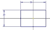 |  |
| 3. | Other Geometry |  |  |
| 4. | Any open sketch |  | 
Note: When an open profile is extruded, the result is always a surface.
|
You might need to make references to the following lessons in order to understand this lesson:
OBJECTIVES
At the end of this lesson, the reader should be able:
- Explain the process of extrusion.
- Understand the principle of the Extrusion Feature in Autodesk Inventor.
- Use the Extrude tool for creating an Extrusion Feature.
- Understand the uses of the Join, Cut, and Intersect options of the Extrude dialog box.
LOCATING THE EXTRUDE TOOL
The Extrude tool could be found on:
- RIBBON: Model tab > Create panel > Extrude
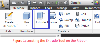
- SHORTCUT: When you are in the Sketch environment and are through with the necessary sketches, simply press "E" on your keyboard to launch the Extrude tool.
BASE SKETCHES & FEATURES
A Base Sketch is the first sketch found on your Model Browser, irrespective of its name. It is the first sketch that was created in the model.
A Base Feature is the first feature created from the base sketch. The base feature is usually a sketched feature (i.e. Extruded, Revolved, Swept, or Lofted features).
CREATING EXTRUDED FEATURES
In this lesson, it is assumed that you are familiar with Inventor's Sketch environment. If you are new to Inventor's Sketch environment, you might have to read previous lessons in this blog. Check out the Table of Contents. The tutorial was created with Inventor 2011.
You might want to read the tutorial on "Boolean Operations in Autodesk Inventor."
In this section, we are going to create a Front Frame part for an infant scooter.
BASE FEATURE
- Open the dataset file Front_Frame_Extrusion_Lesson.ipt. The file was created with Inventor 2011 to ensure compatilibility with newer versions of Inventor.
- Press E to launch the Extrude tool. Alternatively, go to Model tab > Create panel > Extrude tool.
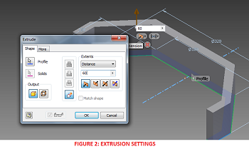
- Click on the Left and Right profiles. Set the extrusion distance to 60mm, and click OK to finish.
This is the base feature.

SECOND SKETCH AND FEATURE
Now, we are going to create a second sketch and second feature.
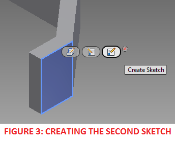
- Click on the right-hand side of the base feature as shown in Figure 3. Click Create Sketch on the mini-toolbar to create a new sketch using the selected planar face.
- Press Page Up and click on the planar face shown in Figure 3 to Look At the face.
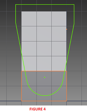
- Create the geometry as shown in Figure 4.
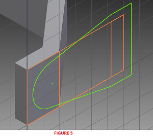
- Launch Project Geometry: Sketch tab > Draw panel > Project Geometry.
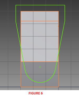
- Project the edges of the face next the face on which the current sketch is based. Refer to Figures 5 and 6 for guidance.
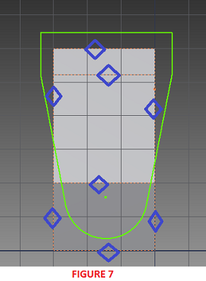
- Next we convert all the projected (or reference geometry) to construction geometry. Select all the projected geometry.
- Go to Sketch tab > Format panel and click Construction. See Figure 7.
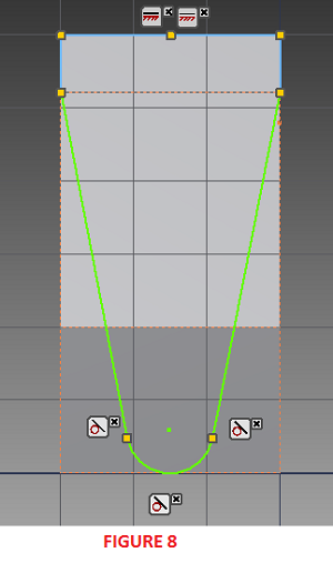
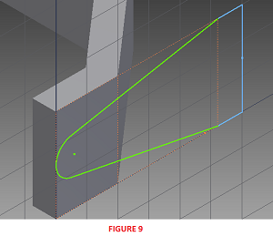
- Apply geometric constraints as shown in Figure 8. The completed sketch should be as shown in Figure 9.
- Now, we are through with our sketch. Let's create the extrusion. Press E to launch the Extrude tool.
- On the Extrude dialog, set Extents to All. Also set the Boolean operation to Intersect.
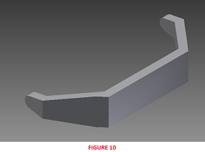
- Click OK to finish the extrusion. The resulting solid is shown in Figure 10.

In the next lesson, we are going to explore the Extents options found on the Extrude dialog box.
0 komentar:
Posting Komentar